

Restriction Orifice (RO) – Flow Control Solutions by Fluid Tech
Solutions for Slurry Systems with Restriction Orifice (RO)
Slurry services can be unforgiving. Anyone who has spent time around abrasive mineral slurries, fine tailings, or thick industrial mixtures knows how quickly a control valve can be chewed up when velocities spike or cavitation sets in. That’s exactly where a well-engineered Restriction Orifice (RO) becomes invaluable.
At Fluid Tech, we design and size ROs for real-world operating conditions. Our focus is simple: give your control valves a longer, safer, and more predictable service life while keeping your flow control stable and manageable.
Whether you’re dealing with high solids, pressure fluctuations, or persistent cavitation challenges, a properly engineered Restriction Orifice can dramatically change how your system behaves. And when it’s done with accurate modelling – not guesswork – the improvement is immediate and measurable.
Need Vales, Valve Repairs / Reconditioning? Call us on 082 414 6756

How Slurry Service Damages Control Valves
Slurries don’t behave like clean liquids. The mix of particles, viscosity shifts, and turbulence means components always take a beating. Fluid Tech sees the same patterns across multiple industries:
High-Velocity Particle Attack
When flow accelerates at a throttling point, solid particles gain momentum and strike the valve trim surfaces. Over time, this impact causes scoring, pitting, and severe metal loss.
Cavitation Loading
Where pressure drops too sharply, it may fall below the fluid vapour pressure. Vapour bubbles form at the vena contracta and collapse violently downstream. These micro-jets, often exceeding 1,000 MPa, destroy stainless steel and elastomers with ease.
Unstable Pressure Recovery
When recovery is aggressive, jetting behaviour amplifies, creating more turbulence and accelerating wear.
All of these issues shorten the life of a control valve, increase downtime, and raise maintenance costs, especially in mines, chemical plants, wastewater facilities, and any operation handling abrasive mixtures.
Masoneilan Rotary Control Valves
Eccentric Plug
35002 Series Camflex II

PFA Lined
31000 Series

Triple Offset Butterfly
33000 Series

Swing-Through Butterfly
37002 Series Minitork™ II

Why a Restriction Orifice (RO) – Flow Control Instrument Works So Well
An RO doesn’t replace the control valve. Instead, it shares the workload.
Instead of one extreme pressure drop across the valve, the loss is distributed more intelligently across two points. This controlled pressure staging lowers fluid velocity and softens cavitation intensity.
Fluid Tech’s modelling demonstrates that this approach creates:
- Two gentler vena contracta regions instead of one aggressive point
- Reduced ΔP at the valve trim, allowing the valve to operate within a safer window
- More stable flow regimes, especially in systems prone to cavitation onset
- Significantly lower erosive velocities
The RO becomes a passive protector that operates quietly in the background, extending valve life without adding any moving parts or control complexity.
Technical Basis Behind RO Sizing (And Why Accuracy Matters)
An RO only works as intended when its sizing is based on correct physics, not thumb rules. Fluid Tech calculates all essential pressure and velocity parameters using the same cavitation and control valve principles referenced in international ISA/IEC standards.
We Solve for Key Pressures
Our engineers calculate DPS (Downstream Pressure for Severe Cavitation)
It’s the predicted downstream pressure at which fully developed (severe) cavitation will occur.
- p1 = upstream pressure
- pv = liquid vapour pressure
- pc = critical pressure of the fluid
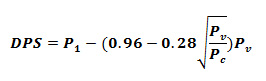
The formula calculates the pressure limit where a valve will move from incipient cavitation into severe/choked cavitation.
Interaction Between Valve and RO
The RO must protect the valve at all load conditions, including:
- High upstream pressure
- Partial valve opening
- Load changes
- Backpressure variation
That’s why our approach models the entire operating envelope, not a single point on a flow curve.
This ensures the RO prevents excessive valve opening, throttling damage, and cavitation onset across all realistic flow scenarios.
Velocity Analysis
Slurry systems behave differently as velocity climbs. Using:
we determine where velocities exceed erosion thresholds. When required, the RO diameter is adjusted using Cv-derived calculations that stabilise the jet expansion profile and keep the Beta ratio within a safe band.
Masoneilan Reciprocating Control Valves
Double Seated Globe Valve
10000 Series

Globe & Angle Top-Guided Valve
21000 Series

Micro-Trim Globe Valve
28000 Series VariPak™

Globe & Angle Cage-Guided Valve
41005 Series

Where a Restriction Orifice (RO) Makes the Biggest Difference
You will see dramatic improvements in systems where:
- The valve is continually exposed to abrasive solids
- Process pressure drop is too high to pass through a single control valve
- Cavitation has already damaged trims or pipes
- Flow stability is inconsistent
- Maintenance teams are replacing valves more often than expected
Typical applications include:
- Mineral slurry pipelines
- Tailings transfer
- Chemical slurries
- Thickened wastewater
- Lime and ash systems
- Desalination plant brine management
- High-solids industrial effluents
When your flow profile is aggressive enough to chew through hardened trims, a Restriction Orifice becomes one of the most cost-effective protective measures you can add.
How Fluid Tech Engineers Your RO for Reliable Performance
Every RO we design starts with process data from your actual system. The modelling software used by Fluid Tech reads real values – density, vapour pressure, ΔP distribution, flow regime – and calculates optimum orifice size from first-principles equations.
Our Engineering Workflow
- Full Cavitation Risk Assessment
We evaluate valve operation against:
- Critical pressure ratio
- Cavitating flow thresholds
- DPS (Downstream Pressure for Severe Cavitation)
- Vena contracta behaviour
This highlights whether the existing valve is at risk under any part of its travel.
- Dynamic Pressure Drop Distribution
Rather than assigning arbitrary ΔP values, the model calculates where the pressure naturally wants to fall, then shifts the peak to the RO so that the valve never sees destructive pressures.
- Velocity Threshold Checks
The software flags when line velocity approaches erosive limits, particularly important in slurry pipelines where pipe wall thinning becomes a safety issue.
- Orifice Geometry Selection
Once the required ΔP and velocity limits are known, we finalise:
- Orifice diameter
- Plate thickness
- Edge design (sharp, quarter-round, conical)
- Material suitability for slurry abrasion
This ensures the RO performs consistently without introducing excessive turbulence.
- Installation Integration
The position, upstream or downstream of the valve, depends on the system’s flow regime.
In many slurry circuits, downstream installation reduces cavitation damage at the valve exit. In others, upstream installation protects the valve body itself. Each case is calculated individually.
Need Vales, Valve Repairs / Reconditioning?

Masoneilan Severe Service Control Valves
Angle Valve with Lo-dB and V-LOG Trim
72000 Series

Multi-Stage Valves (Angle/Globe)
77003 Series

LincolnLog
78400/18400 Series

Globe & Angle Style with Lo-dB / V-LOG Trim
49000 Series

Results You Can Expect After Installing a Restriction Orifice
When an RO is modelled correctly, the difference is immediate and measurable.
- Lower Maintenance Costs
Valves no longer suffer accelerated erosion, meaning fewer trim replacements, less downtime, and lower risk of unplanned shutdowns.
- Improved System Stability
Pressure fluctuations soften, making the system easier to manage and more predictable during load changes.
- Safer Pressure Profiles
Two controlled pressure-drop points prevent catastrophic collapse pressures that can destroy valve internals and downstream piping.
- Longer Valve Lifespan
With destructive cavitation removed from the valve body, service life extends significantly – often doubling in demanding slurry applications.
- Zero Mechanical Wear
The RO has no moving components. Once installed, it performs reliably with almost no maintenance.
As the Fluid Tech document notes, ROs offer a measurable economic advantage when compared with continually replacing exacerbated trims or moving to exotic alloys unnecessarily.
Why Work With Fluid Tech?
Fluid Tech specialises in engineered flow control for tough industrial environments -from slurry operations and mine processing to chemical and wastewater systems. Our engineers approach each application with real data and deterministic calculations. No guesswork. No quick fixes.
When you work with us, you get:
- A Restriction Orifice designed from first-principles physics
- Detailed modelling of your actual system behaviour
- Protection for both the control valve and downstream piping
- A smoother operating envelope
- Long-term reliability, not temporary solutions
If your valves are wearing out faster than expected, or if cavitation is a recurring headache, we’ll help you stabilise the system and extend equipment life.
Ready to Improve Your System’s Reliability?
Whether you’re looking for a single Restriction Orifice (RO) – Flow Control Instrument or a complete assessment of your control valve performance, Fluid Tech is ready to help.
If you’d like us to analyse your slurry system, review your control valves, or design a custom RO based on your process data, reach out to us.
Contact Fluid Tech today
Request a consultation, send your process conditions, or chat with our engineering team – let’s help you protect your valves and stabilise your flow control system.
Need Vales, Valve Repairs / Reconditioning? Call us on 082 414 6756
Need Valve Repairs / Reconditioning?
Download our certificates here:
📞 Contact us today to book testing, emergency repair, or predictive asset management support.